Determine a Safe and Efficient Element Watt Density
Element Watt Density is the wattage dissipated per square inch of the element sheath surface and is calculated with the following formula:
| Watt Density = | element wattage |
| π × element dia. × element heated length |
For a particular application, element watt density will govern element sheath temperature. Factors to consider when choosing a suitable watt density are:
- Many materials are heat sensitive and can decompose or be damaged if the element is running too hot.
- Air and other gases that are poor conductors of heat require watt densities matched to the velocity of the gas flow to prevent element overheating.
- When heating hard water and cleaning solutions, mineral deposits can build up on the element sheath, acting as a heat insulator and raising the internal element temperature. If these deposits cannot be periodically removed, use a lower watt density element to increase heater life expectancy.
Determine Pressure-Temperature Rating of Flange Required
| Temperature °F (°C) | ||||||||||||||
|---|---|---|---|---|---|---|---|---|---|---|---|---|---|---|
| Flange | -20 to 100 | 200 | 300 | 400 | 500 | 600 | 650 | 700 | 750 | 800 | 850 | 900 | 950 | 1000 |
| Material | (-28.9 to 37.8) | -93.3 | -148.9 | -204.4 | -260 | -315.6 | -343.3 | -371.1 | -398.9 | -426.7 | -454.4 | -482.2 | -510 | -537.8 |
| A105 Steel | 285 | 260 | 230 | 200 | 170 | 140 | 125 | 110 | 95 | 80 | — | — | — | — |
| 316 Stainless | 275 | 240 | 215 | 195 | 170 | 140 | 125 | 110 | 95 | 80 | 65 | 50 | 35 | 20 |
| 304 Stainless | 275 | 235 | 205 | 180 | 170 | 140 | 125 | 110 | 95 | 80 | 65 | 50 | 35 | 20 |
NOTE: Preconfigured and stock heaters listed on the website have Class 150-lb flanges. For heaters with a higher Pressure-Temperature Rating consult Tempco.
Select the Element Sheath Material
CORROSION: In addition to selecting a sheath material that is compatible with the heated medium, other factors that affect corrosion need to be considered:
- The temperature of the corrodent— As temperature increases the degree of corrosion increases. Also remember that usually the element temperature is higher than the material it is heating.
- The degree of aeration to which a corrodent is exposed— Stagnant conditions can deprive the stainless steels of oxygen, which is required to maintain their corrosion resistant surface.
- Velocity of the corrodent— Increased velocity can increase the corrosion rate.
For additional information see our Sheath Material Selection Guide from the engineering section of our catalog.
Standard Element Sheath Materials
- Incoloy® 800— A Nickel (30-35%), Chromium (19-23%), Iron alloy. The high nickel content of this alloy contributes to its resistance to scaling and corrosion. Used in air heating (also see Incoloy® 840) and immersion heating of potable water and other liquids that are not corrosive to an Incoloy® 800 sheath.
- Low Carbon Steel— Applications include fluid heat transfer media, tar, high to low viscosity petroleum oils, asphalt, wax, molten salt, and other solutions not corrosive to a steel sheath.
- 316 Stainless Steel— A Chromium (16-18%), Nickel (11-14%), Iron Alloy with Molybdenum (2-3%) added to improve corrosion resistance in certain environments, especially those that would tend to cause pitting due to the presence of chlorides. Applications include deionized water.
- Copper— Mainly used in clean water heating for washrooms, showers, rinse tanks and freeze protection of storage tanks.
Optional Element Sheath Materials
- 304 Stainless Steel— A Chromium (18-20%), Nickel (8-11%), Iron Alloy used in the food industry, sterilizing solutions, air heating and many organic and inorganic chemicals.
- 321 Stainless Steel— A Chromium (17-20%), Nickel (9-13%), Iron Alloy modified with the addition of titanium to prevent carbide precipitation and the resulting intergranular corrosion that can take place in certain mediums when operating in the 800-1200°F (427-649°C) temperature range.
- Incoloy® 840— A Nickel (18-20%), Chromium (18-22%), Iron alloy. Incoloy 840® has about 10% less nickel than Incoloy 800. Used in many air heating applications where it has exhibited superior oxidation resistance at less cost than Incoloy 800®.
- Incoloy® 825— A Nickel (38-46%), Chromium (19.5-23.5%), Molybdenum (2-3%) Iron alloy. Consult Tempco for more information.
Surface Treatments for Stainless Steel and Incoloy® Elements and other Wetted Parts to Improve Corrosion Resistance
Flanged Immersion Heater surfaces in contact with the material being heated can be passivated or electro-polished to improve their resistance to corrosion.
Passivation removes surface contamination, usually iron, so that the optimum corrosion resistance of the stainless steel is maintained. Surface contamination would come from the small amount of steel that may be worn off a tool during the manufacturing process. Passivating is accomplished by dipping the heater in a warm solution of nitric acid.
Electro-Polishing is an electrochemical process that removes surface imperfections and contaminants, enhancing the corrosion resisting ability of the stainless steels. The resultant surface is clean, smooth and bright. Many medical and food applications require this finish.
Select Optional Flange and Gasket Materials
Optional flange materials include:
- 304, 304L Stainless Steel
- 316L Stainless Steel
- Incoloy® 800
Gaskets
Gaskets of different types, including spiral wound metal with non-metallic filler, are available to properly seal any flanged heater. Gasket material choice depends on operating conditions and fluid compatibility. Consult TEMPCO for help with your selection.
Select Terminal Housing
Type 1N Terminal Box
- NEMA 1 rating
- For heaters having no thermostat
- Supplied with all Preconfigured and Stock Heaters
- All flange sizes
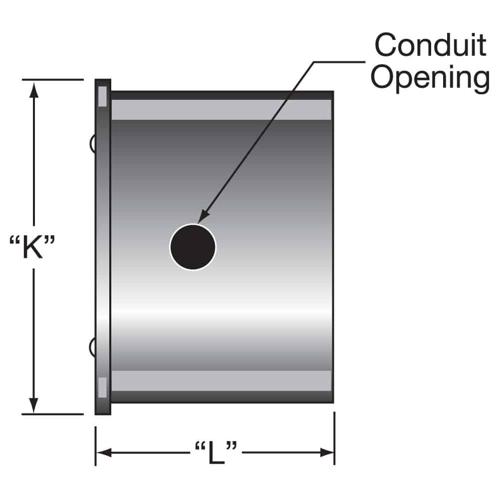
| Flange Size | “K” | “L” | Conduit Opening | ||
|---|---|---|---|---|---|
| in | mm | in | mm | ||
| 3 | 4-1/8 | 105 | 3-1/16 | 78 | 1-1/8 |
| 4 | 6 | 152 | 4 | 102 | 1-1/8 |
| 5 | 6-3/8 | 162 | 4 | 102 | 1-1/8 |
| 6 | 7-13/16 | 198 | 5-3/8 | 137 | 1-1/8 |
| 8 | 9-7/8 | 251 | 5-3/8 | 137 | 1-3/8 |
| 10 | 11-3/4 | 298 | 6 | 152 | 1-3/4 |
| 12 | 13-3/4 | 349 | 6 | 152 | 1-3/4 |
| 14 | 15-1/4 | 387 | 6 | 152 | 1-3/4 |
Type 1T Terminal Box
- NEMA 1 rating
- For heaters with thermostat
- Supplied with all Preconfigured and Stock Heaters
- All flange sizes
| Flange Size | “K” | “L” | Conduit Opening | ||
|---|---|---|---|---|---|
| in | mm | in | mm | ||
| 3 | 4-1/8 | 105 | 6 | 152 | 1-1/8 |
| 4 | 6 | 152 | 6 | 152 | 1-1/8 |
| 5 | 6-5/8 | 168 | 6 | 152 | 1-1/8 |
| 6 | 7-13/16 | 198 | 6 | 152 | 1-1/8 |
| 8 | 9-7/8 | 251 | 6 | 152 | 1-3/8 |
| 10 | CALL TEMPCO | ||||
| 12 | |||||
| 14 | |||||
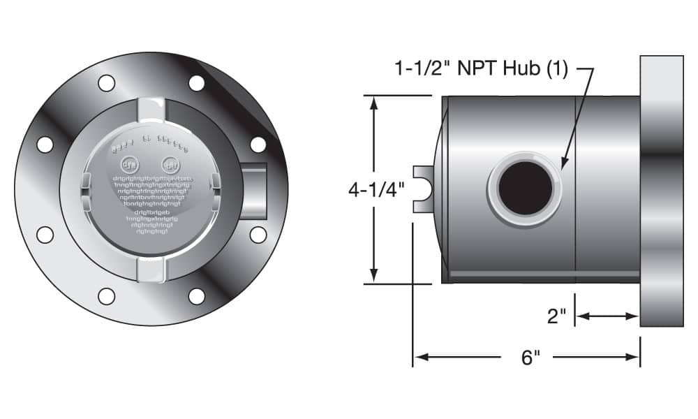
Type 2N Terminal Box
- NEMA 4 rating
- For heaters having no thermostat
- 3 inch flanges
- Requires the use of the cover gasket
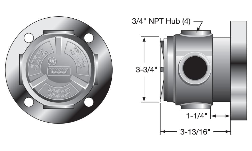
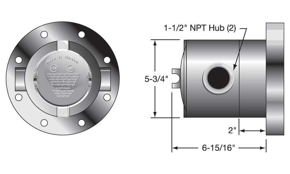
Type 2T Terminal Box
- NEMA 4 rating
- For heaters with thermostat
- 3 inch flanges
- Requires the use of the cover gasket
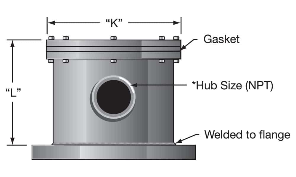
Type 3N Terminal Box
- NEMA 4 rating
- For heaters having no thermostat
- 4 and 5 inch flanges
- Requires the use of the cover gasket
Type 3T Terminal Box
- NEMA 4 rating
- For heaters with thermostat
- 4 and 5 inch flanges
- Requires the use of the cover gasket
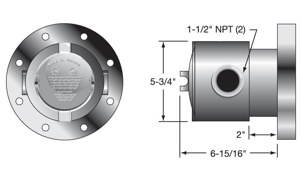
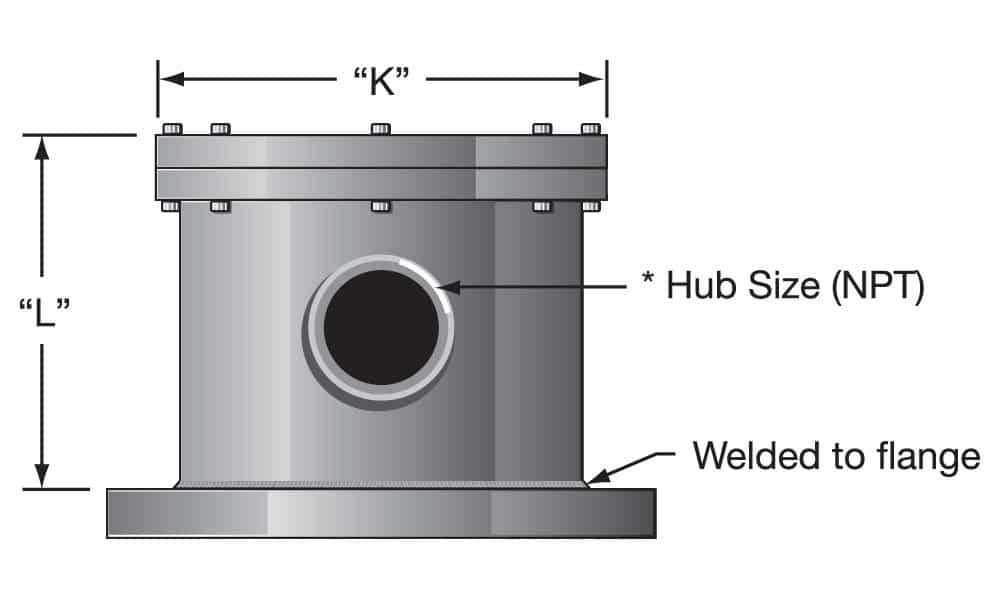
Type 4N Terminal Box
- NEMA 4 rating
- For heaters having no thermostat
- 6 through 14 inch flanges
| Flange Size | “K” | “L” | Conduit Opening | ||
|---|---|---|---|---|---|
| in | mm | in | mm | ||
| 6 | 8 | 203 | 6 | 152 | 2 |
| 8 | 10 | 254 | 6 | 152 | 2 |
| 10 | 13-3/4 | 349 | 6 | 152 | 2-1/2 |
| 12 | 15-5/8 | 397 | 6 | 152 | 2-1/2 |
| 14 | 17-1/4 | 438 | 6 | 152 | 2-1/2 |
Type 4T Terminal Box
- NEMA 4 rating
- For heaters with thermostat
- 6 through 14 inch flanges
| Flange Size | “K” | “L” | Conduit Opening | ||
|---|---|---|---|---|---|
| in | mm | in | mm | ||
| 6 | 8 | 203 | 6 | 152 | 2 |
| 8 | 10 | 254 | 6 | 152 | 2 |
| 10 | 13-3/4 | 349 | 7-1/2 | 191 | 2-1/2 |
| 12 | 15-5/8 | 397 | 7-1/2 | 191 | 2-1/2 |
| 14 | 17-1/4 | 438 | 7-1/2 | 191 | 2-1/2 |
Type 5N Terminal Box
- NEMA 7 rating
- For heaters having no thermostat
- 6 through 14 inch flanges
| Flange Size | “K” | “L” | Conduit Opening | ||
|---|---|---|---|---|---|
| in | mm | in | mm | ||
| 6 | 9-3/8 | 203 | 6 | 152 | 2 |
| 8 | 11-1/2 | 254 | 6 | 152 | 2 |
| 10 | 13-3/4 | 349 | 6 | 152 | 2-1/2 |
| 12 | 13-5/8 | 397 | 6 | 152 | 2-1/2 |
| 14 | 17-1/2 | 438 | 6 | 152 | 2-1/2 |
Type 5T Terminal Box
- NEMA 7 housing
- For heaters with thermostat
- 6 through 14 inch flanges
| Flange Size | “K” | “L” | Conduit Opening | ||
|---|---|---|---|---|---|
| in | mm | in | mm | ||
| 6 | 9-3/8 | 203 | 7-1/2 | 191 | 2 |
| 8 | 11-1/2 | 254 | 7-1/2 | 191 | 2 |
| 10 | 13-3/4 | 349 | 7-1/2 | 191 | 2-1/2 |
| 12 | 13-5/8 | 397 | 7-1/2 | 191 | 2-1/2 |
| 14 | 17-1/2 | 438 | 7-1/2 | 191 | 2-1/2 |
Explosion resistant terminal housings are intended to provide containment of an explosion in the enclosure only. No portion of the heater assembly outside the enclosure is covered under this NEMA rating. Abnormal use of a heater which results in excessive temperature can create hazardous conditions such as a fire. Never perform any type of service nor remove the housing cover prior to disconnecting all electrical power to the heater
Complete heater details and additional options:
Related Product Lines:
